To point something at something consistently over time you need a way to determine where it is pointed, a way to point where it’s wanted and a way to determine how fast it needs to change. In this case it is a rocket that needs to be pointed upwards. We’ll use the GY521 accelerometer and gyroscope to determine pitch,yaw and roll, and servos attached to fins at the bottom of the rocket to adjust direction as needed. To avoid overcorrection we’ll most likely use some sort of PID-controller.
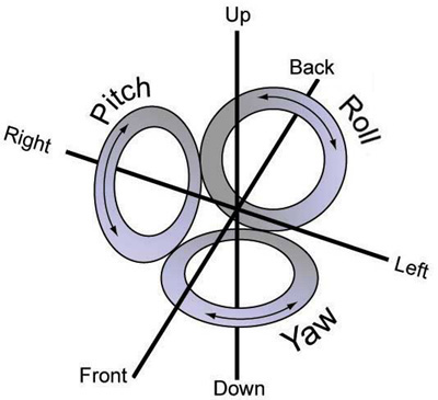

The GY521 breakout board uses a MPU6050 accelerometer that detects changes in acceleration and rotation. That means it detects movement in all directions without rotation and detects rotation around its three axis. For our purpose, we want the gyro to keep stable at 0 degree rotation around the x and y axis, that is the pitch and roll. We will want to implement some controll of the z-axis, or yaw, as well to keep it from spinning out of control, but for now the x and y axis will be our main focus.
I will use two SG90 servos to control my fins. The nice thing about those servos is that they are cheap, and that code for servos usually is the same no matter which servo you use. That means that if I need to replace them with something faster, stronger or both later on, I won’t have to make any edits in my code (maybe).
Here’s the general idea:
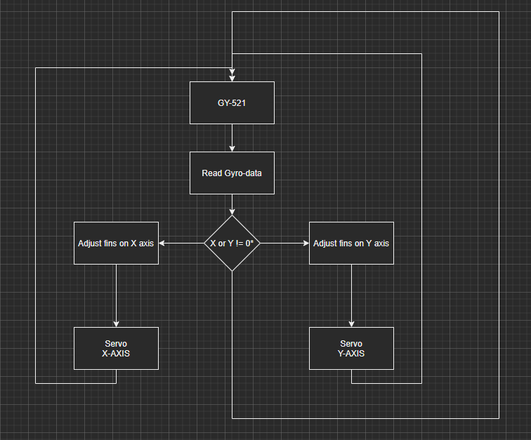
So, as you can read from my marvelous diagram, the idea is a loop that reads a value from the gyroscope and determines if the value is different from the desired value. I if it, we need to determine which axis it is different on (could be both) and adjust the angle of the fin by instructing the servos to move accordingly. Let’s start by reading the sensor.
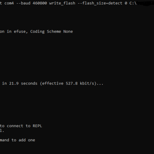
BREAKING NEWS! Or just broken board! My TTGO LoRa32 that was designated for this project is giving me the silent treatment. That means I cannot use the REPL or upload files to it, so I have to use my arduino instead. That means that for the remainder of this post, and probably for the remainder of this post-series I will be using arduino. I will redo this with micropython at some later time, so stay tuned! Have a look here: I “bricked” my TTGO LoRa32 board
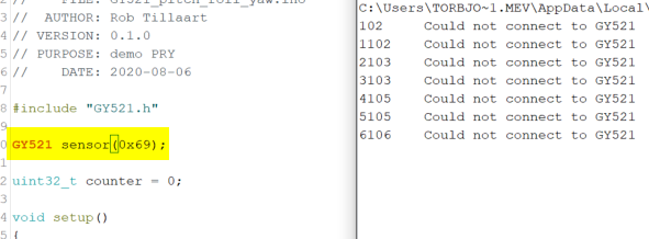
The sensor communicates over I2C, so we’ll need to attach it to the SDA and SCL pins on the development board. The arduino duemilanove that I’m using (my very first dev board!) is using analog pin 4 for SDA and analog pin 5 for SCL, so I’ll attach the sensor to those pins plus ground and 5v. Next, I’ll use the GY521 library from Rob Tillaart found in the library manager called GY521 (I love it when things are named logically). His library even has an example called GY521_pitch_roll_yaw, so I’ll test that to see if the sensor is working.
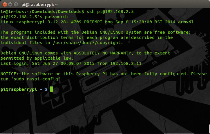
The first try did not work so well. It seems the example states the wrong I2C address for the sensor, so the arduino was unable to find it.
Ah, much better! So, the sensor is readable and responsive. Let’s move on to the next step!
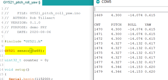
I have attached the servos to pins 6 (X-axis, or the fins controlling pitch) and 5 (Y-axis, or the fins controlling yaw). To control the servos is simply a matter of creating an instance of the servo, attaching a pin and write out the servo position in degrees using the servo library. You could do PWM or similar, and there might be some benefits and microoptimalization we could do around this, but that will have to come later. I made this lovely diagram to display how the gyro and servos work together. Everything above the horizontal line is gyro position. It just dawned on me that my diagram assumes the rocket will face nose up at all times… Well, not the worst assumption regardless of if we want to land it with parachute, EDF or another rocket. So, the readings from the example code from the gy521 library showed that each gyro reading was close to 0 when the sensor lied flat on a surface. Tilting it gave negative values one way, and positive values in the opposite direction. That means the servo will have to be at 90 degrees when the gyro reading for that axis shows ~0 degrees. You get the idea.
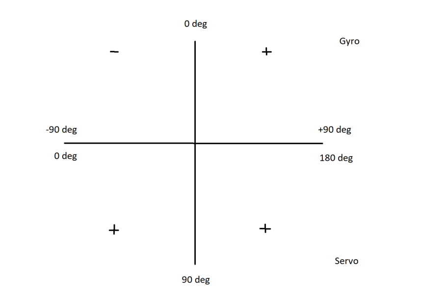
And intuitively I just want to write the position of the gyro to the servo + 90 degrees. That gives servo position 0 when gyro reads negative 90, servo position 90 when gyro reads 0 degrees, and servo position 180 when gyro reads 90 degrees. I also add a check to see if value from calculating servo position is over 180 or under 0 to keep a max rotation on the fins. It should maybe be a little bit lower, but if the fins are maxing out I guess the rocket is pretty much done for either way.
Here’s my implementation in code. I start by getting a new reading from the sensor, collect the angles for my two fins and start translating it into degrees for the servos. Then I check if the angle calculated exceeds the angle possible by the servo and cap it before I write it to the servo.
void adjustFins(){
    mpu6050.update();
    double gyrX = mpu6050.getAngleX();
    double gyrY = mpu6050.getAngleY();

    //direct translation
    int valX = (int)gyrX + 90;
    if(valX < 0){
      valX = 0;
      }
    if(valX > 180){
      valX = 180;
      }

    int valY = (int)gyrY + 90;
    if(valY < 0){
      valY = 0;
      }
    if(valY > 180){
      valY = 180;
      }

    finX.write(valX);
    finY.write(valY);
  }
And that’s all there is to it! I will write a new blog post taking off from where I left this where I will implement a PID controller for the servos so that they might work a little smoother. Also, I need to start looking at the telemetry part of the rocket and data logging, so stay tuned for that as well!
